















































































Electronic Fencekey points on how to install:
1 Principles
1) One Zone is one series loop; the connection from the host to the Electronic Fence must be series, not parallel.
2) Wire crossover points must use high-voltage-resistant wire to avoid insufficient clearance or short circuits. Therefore, in the following four situations:
(1) the connecting wire from the host's high-voltage output end to the start of the Electronic Fence; (2) the crossover wire from the upper conductor of the Electronic Fence to the lower conductor; (3) the connecting wire from the end of the Electronic Fence back to the host; (4) the connecting wire between two adjacent sections of Electronic Fence, all must use high-voltage-resistant insulated wire with a rated withstand voltage of no less than 20KV.
3) Regarding grounding, the grounding point is generally selected at the end of the Electronic Fence. However, when a lightning arrester is added to the Zone, the grounding point of the arrester should be at the start of the Electronic Fence.
4) The high-voltage system and lightning arrester must have good grounding, with a grounding resistance<of 10 ohms.
5) The high-voltage and low-voltage grounds must be separated by at least 4m.
2 Installation key points
1) The fence wires should be fixed in sections. It is recommended to divide a straight line or the same Zone into one section; wires not on the same straight line should be installed in several passes.
2) Unreel the alloy wire: use a reel rack or appropriate method to unreel; do not unreel arbitrarily to avoid tangling and unevenness. Four wires can be unreeled simultaneously, but take care not to cross them.
3) Tension the wire: fix one end of the alloy wire to the terminal post insulator at one end using a wire-to-wire connector (or self-winding), then place the 4 alloy wires correspondingly into the wire slots of the intermediate post insulators or load-bearing post insulators, finally thread them through a tensioner, pull the alloy wires tight and fix them to the terminal post insulator at the other end with a wire-to-wire connector (or self-winding). Then adjust the tensioner so that the 4 wires are taut simultaneously and parallel to each other. Multiple parallel wires should be tensioned simultaneously.
3. Grounding electrode fabrication
A grounding electrode must be driven under each host, and a grounding electrode should be installed every 100m. Standard grounding electrode: standard galvanized grounding angle steel greater than 40x40x4x1500mm (with a grounding bolt or hole of M10 or above), driven vertically into the ground. The grounding electrode should be reliably connected to the lightning arrester bracket and the grounding end of the booster, with a grounding resistance<of 10 ohms. If insufficient, a resistance-reducing agent can be added. The high-voltage ground and low-voltage ground must be isolated from each other and must be>4m apart.
4. Laying of RS485 signal control cables and fence controller power cables
If pre-embedded conduits exist, they can be used directly; otherwise, use PVC conduits for conduit laying. The laying requirements must meet conduit wiring requirements. The conduits mainly contain: RS485 signal control cable RVSP 2x0.75mm round twisted pair, and fence controller power cable RVV 2x1.5mm sheathed cable (branched from the host to each fence controller; if the distance exceeds 600m, the wire gauge must be increased).
5. Installation of warning signs
Install a""Electronic Fence - No Climbing""warning sign, which can be fixed to the fence wire with alloy wire.
6. Installation of the fence controller (host)
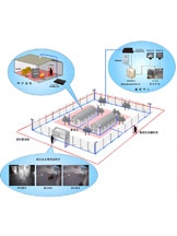
1) Install the fence controller below the fence at the fence division point (the position marked in the drawing), keeping the fence controller about 40cm from the fence, and fix it to the wall with expansion bolts. 2) Make a good connection between the fence controller and the grounding flat iron. The fence controller ground (low-voltage ground, connected to the communication line shield) should be isolated from the high-voltage fence ground (high-voltage ground) to avoid interference. 3) Connect the high-voltage lead of the fence controller to the fence through a PVC conduit, and reliably connect the joints with wire-to-wire connectors (or self-winding). 4) Keep the RS485 bus, alarm output wires and power wires separate from the high-voltage wires, using separate conduits. 5) Reliably connect the high-voltage lightning arrester between the start of the perimeter fence and the ground wire (note the waterproofing direction).
8. RS232 communication between the host and computer: simply add an RS232-to-RS485 conversion module at both ends of the host and computer.
Basic installation modes
The basic installation modes are divided into three types: wall-top installation, attached installation and ground-mounted installation. Details are as follows:
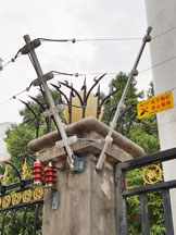
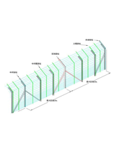
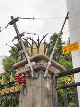
Wall-top installation is erected above the top of an existing perimeter wall and can be installed vertically or at an inclined angle. The wall should be higher than 2m. The Electronic Fence is about 0.8m high; the distance from the top wire of the Electronic Fence to the wall>is 750mm, and the distance from the bottom wire to the wall top is 150mm +/- 20mm.
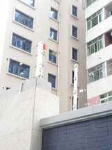
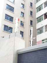
Attached installation: In the national standard "Pulse Electronic Fence and Its Installation and Safe Operation" (GB/T 7946-2008), the definition of attached installation is "attached, i.e., attached to the upper part or inner side of a wall or fence; the distance from the topmost metal conductor of the Pulse Electronic Fence front end to the wall top or fence top should be no less than 700mm."
Attached installation is mainly used where there are higher safety-level requirements without consuming the owner's outer land; some walls with uneven tops also require attached installation. This method has three requirements for the existing wall: first, the wall must be strong enough to withstand the pulling force of the Electronic Fence; second, the wall must be higher than 2m; third, the mesh of the wall must be<50mm, to prevent hands from reaching in and touching the Electronic Fence attached to the inner side of the wall.
Ground-mounted installation
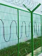
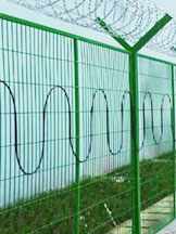
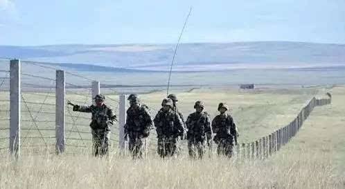
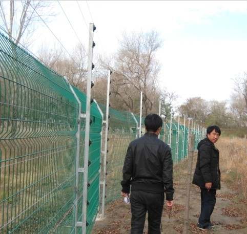
The definition of ground-mounted in the national standard is: the Pulse Electronic Fence front end is independently installed around the building as a physical barrier, and the height of the Pulse Electronic Fence front end should be no less than 1800mm.
This installation method usually applies where there is no building perimeter or clear perimeter marking on site, so the front end of the fence, composed of support posts plus alloy wire, must be used to form a protected area. This requires that the top height of the fence front end be no less than 1.8m, the number of wires reach 12-20 or even more, and the wire-to-wire spacing be controlled between 120-150mm.
Installation in special environments: undulating drops, large wall pier crossovers, drop wall wire patching, river-edge blind spots, numerous turns, and gate fences.
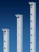
The front-end part of the Electronic Fence is an important component of the Electronic Fence system. After fully investigating customers' actual usage, Guangtuo launched a new Electronic Fence front end. Compared with the previous classic models, the new Electronic Fence front end has a more beautiful and fashionable appearance, easier installation, and enhanced strength and firmness.
- Previous: A Pulse Electronic Fence Can Be Installed Along Undulating Terrain
- Next: What Is the Purpose of Installing an Electronic Fence at a Substation?
Please contact us right away or call the hotline: +86-13590284141. We will answer all your questions in detail. Project Manager Online