
















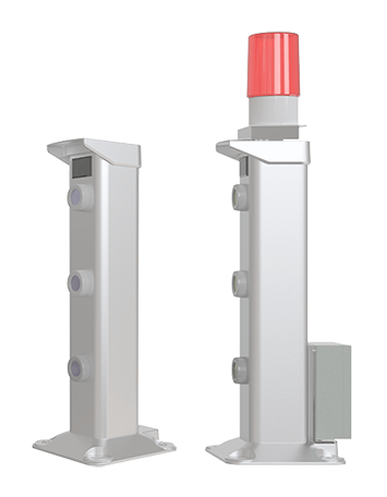
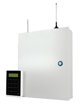


































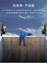






















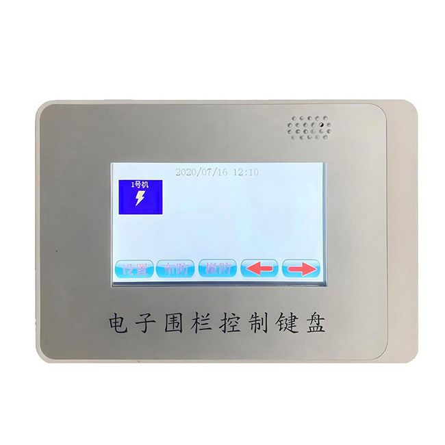
- Photos & Details
- Specifications
Preface
This guide aims to provide standardized and detailed operational specifications for pulse electronic fence installation and construction personnel, property operation and maintenance personnel, and security engineering and technical personnel. It covers the entire process from installation preparation, on-site construction, system commissioning to daily operation and maintenance, and fault handling. The guide is strictly compiled in accordance with relevant national standards such as "GB/T 7946-2015 Pulse Electronic Fence and Its Installation and Safe Operation". It is applicable to pulse electronic fence systems in various scenarios (such as prisons, campuses, industrial parks, residential areas, warehousing and logistics parks, etc.), aiming to ensure the quality of system installation, enhance operational stability, prolong equipment service life, and fully leverage its active defense and security alarm functions.
I. General Provisions
1.1 Scope of application
This guideline is applicable to the installation and construction of new and renovated projects for AC pulse electronic fence systems (single and multiple zones), as well as daily inspections, maintenance, fault diagnosis, and emergency handling after commissioning. It is not applicable to high-voltage power grid-type hazardous protective equipment, and relevant operations must be carried out by security personnel with professional qualifications.
1.2 Reference standards and basis
1. GB/T 7946-2015 "Pulse Electronic Fence and Its Installation and Safe Operation"
2. GB 50348-2018 Technical Standard for Engineering of Security and Protection System
3. GB 50198-2011 Technical Code for Engineering of Civil Closed-Circuit Monitoring Television System
4. GB/T 16571-2012 "Requirements for Security and Protection Systems of Cultural Relics Protection Units" (for special scenarios)
II. Preparation before installation
2.1 On-site investigation and scheme design
1. Core points of on-site inspection:
① Clarify the protective boundary: Confirm the starting and ending points, as well as the total length of the fence installation, and mark surrounding obstacles (trees, utility poles, walls, underground pipelines, etc.) to avoid conflicts during installation;
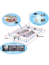
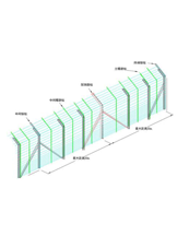
② Scene classification planning: Based on the installation environment, it is divided into fence-type (attached to existing fences), floor-type (sites without fences), and roof-type (roof perimeter protection). The fence height (conventionally 1.8-2.4 meters) and defense zone division (single defense zone length not exceeding 100 meters, which can be shortened to 50 meters for complex scenes) are determined in conjunction with the scene;
③ Environmental risk assessment: For outdoor scenarios, it is necessary to assess the impact of natural factors such as wind and rain, lightning strikes, high temperatures, humidity, coastal salt spray, and ice and snow in the north; for locations close to flammable and explosive areas (such as oil depots and chemical parks), explosion-proof accessories should be used;
④ Confirmation of linkage requirements: Confirm with the customer whether linkage monitoring (automatic video recording/focusing when alarmed), access control (linkage locking), and audible and visual alarm devices (alarm lights/sirens) are required, and reserve corresponding interface positions.
2. Scheme design output: Draw construction drawings, specify column spacing (typically 2-3 meters, shortened to 1.5-2 meters at corners/slopes), wire layers (4-8 wires, adjusted according to protection level), host installation location (preferably indoors in a dry place, outdoor locations require waterproof distribution boxes), line routing (protected through conduits), and warning sign installation points.
2.2 List of Tools and Materials
1. Core tools:
① Measuring tools: laser range finder, tape measure (50 meters), level meter (2 meters), ink fountain (for snapping lines and positioning);
② Installation tools: electric drill (with impact drill bit), angle grinder (for cutting columns/wires), screwdriver set (Phillips/flathead), wire stripper (specially designed for insulated wires), wire crimping tool, wrench set;
③ Testing tools: multimeter (for voltage measurement/continuity check), megohmmeter (for insulation resistance measurement, ≥10MΩ is considered satisfactory), test pen;
④ Auxiliary tools: ladder (2-3 meters), cable tie gun, marking pen, toolkit, gloves (insulated/anti-slip).
2. Core materials:
① Front-end fence accessories: pulse electronic fence host (single/multiple zones, matching the number of zones), upright (stainless steel/aluminum alloy, including fixed base), insulator (ceramic/polymer material, anti-aging/anti-puncture), wire (stainless steel wire/alloy wire, diameter 1.5-2.0mm, tensile strength ≥1500N), wire grip, wire clamp, terminal insulator, intermediate insulator;
② Circuit materials: power cord (RVV 2×1.5mm², copper core), signal cable (RVSP 2×1.0mm², shielded twisted pair, anti-interference), conduit (PVC/galvanized steel pipe, anti-corrosion type for outdoor use), expansion screw (M8-M12, matched according to column specifications), waterproof connector, wiring terminal;
③ Safety and Signage: Warning Signs (size ≥ 30×20cm, white text on a red background, labeled "Danger High Voltage, No Climbing" and "Electronic Fence, No Touching"), Warning Lights/Sirens (optional, for linkage purposes), Waterproof Distribution Box (for outdoor main units).
2.3 Safety protection preparation
1. Construction personnel must hold valid certificates, be familiar with equipment principles and safety operation regulations, wear insulating gloves, safety helmets, and anti-slip shoes, and fasten safety belts when working at heights (on roofs/high walls);
2. Clear away debris in the construction area and set up temporary warning signs (such as "Under Construction - Keep Off") to prevent unauthorized personnel from entering; if construction is to be carried out on existing premises (such as campuses or residential areas), it is necessary to communicate with the management in advance and designate a construction period (to avoid peak traffic times);
3. Check the integrity of tools and equipment: Insulated tools must pass a voltage withstand test, with no damage to the wires. Electric drills, angle grinders, and other power tools should be equipped with leakage protectors;
4. Confirm that the construction power supply is stable, temporary wiring must be standardized, avoid unauthorized and disorderly wiring, and promptly cut off the power after construction is completed.

3、 Standard installation process
3.1 Front end fence installation (core link)
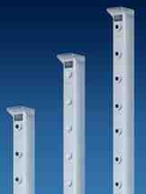
1. Column fixation:
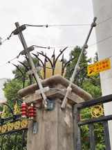
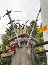
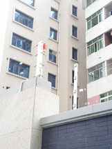
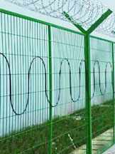
① Wall mounted installation: snap lines at the top of the wall (brick/concrete structure) according to the spacing of the plan, fix the column base to the surface of the wall with expansion screws, and ensure that the base is horizontal; If it is an iron fence, use clamps to fix the base to avoid damaging the fence structure;
② Floor standing installation: excavate a foundation pit on the ground (depth 30-50cm, diameter 20-30cm), place it into the column base, pour concrete (C25 or above), and cure for 24 hours before installing the column; Alternatively, pre embedded anchor bolts can be used for fixation to ensure that the vertical deviation of the column is ≤ 3 ‰;
③ Corner/Terminal Processing: Corner columns need to be installed at corners to increase support strength; Install terminal columns at the terminal, reserve space for wire tightening, and shorten the spacing between columns to 1.5 meters.
2. Installation of insulators:
① Fix the insulator on the column, install the middle insulator on the side of the column (with the wire running horizontally), and install the terminal insulator on the top of the column (with the wire end fixed);
② The installation of insulators should be flat, without looseness, with the insulation surface facing the guide wire side, avoiding direct contact with metal columns (to prevent short circuits); The waterproof performance of insulators needs to be checked in outdoor scenes to ensure that there are no gaps at the interface.
3. Wire installation:
① Wire laying: fix the wire reel on the wire laying rack, lay the wire at a constant speed along the direction of the column, avoid wire tangling/twisting, and reserve a certain tension (to avoid sagging);
② Fixing and tightening: Starting from the terminal column, thread the wire through the terminal insulator slot and fix it with a wire clamp; The middle wire passes through the middle insulator and is temporarily fixed with zip ties or clamps; Tighten the wire with a tensioner at the other end (with tension controlled between 800-1200N to ensure that the wire is straight and not sagging), and permanently fix it with a wire clamp after tightening;
③ Spacing adjustment: The horizontal spacing of the wires is uniform (usually 15-20cm), and they are erected vertically from bottom to top. The distance between the lowest wire and the ground/top of the fence is ≥ 15cm, and the height between the highest wire and the ground/top of the fence meets the requirements of the plan;
④ Special treatment: At the crossing of doors/passages, the wires need to reserve space for movement and use flexible connections (such as wrapping the wires with insulating sleeves to avoid pulling when opening the door); At the slope (slope>15 °), the spacing between columns should be shortened, and the tension of the wires should be adjusted to prevent the wires from slipping.
4. Warning sign installation: Install warning signs in prominent positions on the fence, with one set every 3-5 meters, and must be installed at corners and entrances; Floor standing fences need to be installed on the outside of the fence, while perimeter fences should be installed on the top or outside of the fence to ensure visibility.
3.2 Host and accessory installation
1. Host fixation:
① Indoor installation: Choose a location that is ventilated, dry, without direct sunlight, and easy to operate (such as a security room or power distribution room). Use expansion screws to fix the host to the wall (1.2-1.5 meters above the ground), avoiding close proximity to strong magnetic field equipment (such as frequency converters and large motors);
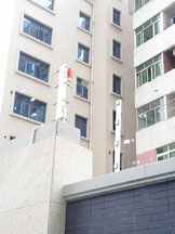
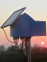
② Outdoor installation: Place the host in a waterproof distribution box and fix it on a column or wall (at least 1.5 meters above the ground to avoid rainwater immersion). The distribution box should be properly grounded, and the inlet should be sealed with a waterproof joint to prevent rainwater from entering.
2. Installation of linkage equipment (optional): The alarm light/signal should be installed near the entrance of the fence or in a visible position in the security room, and securely fixed; Adjust the angle of the surveillance camera to ensure coverage of the fence alarm area and interface with the host alarm output interface.
3.3 Line Connection
1. Power cord connection:
① Host power input: Connect the RVV 2 × 1.5mm ² power cord to the AC220V power supply. Connect the live wire (L), neutral wire (N), and ground wire (PE) to the host power interface, and ensure that the ground wire is reliably grounded (grounding resistance ≤ 4 Ω);
② Line protection: Power lines are protected by conduit, and waterproof conduit is used for outdoor sections. Waterproof tape is wrapped around the joints to avoid short circuits/leakage; Install an air switch (capacity ≥ 10A) in the power circuit to prevent overload.
2. Signal line connection:
① Connection between host and front fence: Use RVSP 2 × 1.0mm ² shielded twisted pair cable to connect the "positive" and "negative" output terminals of the host to the front fence wire. One end of the shielding layer is grounded (host end) to avoid interference caused by grounding at both ends;
② Linkage signal line connection: Use signal lines to connect the host alarm output terminal (NO/NC/COM) with monitoring, access control, alarm lights, and other linkage equipment. Mark the positive and negative poles according to the equipment manual to avoid reverse connection;
③ Multi zone connection: Multi zone hosts need to be connected to each zone fence according to the zone number, and each zone signal line should be independently threaded through pipes to avoid cross interference.
3.4 System Debugging
1. Check before powering on:
① Line inspection: Use a multimeter to measure the continuity of the power line (confirm there is no short circuit), the insulation resistance of the signal line (≥ 10M Ω), and check whether the wiring terminals are tightened and there is no looseness/virtual connection;
② Front end inspection: Clean the weeds and branches around the fence (distance from the fence ≥ 50cm), check that the wires are not broken, the insulators are not damaged, and the warning signs are installed in place;
③ Host inspection: Confirm that the power switch of the host is in the "OFF" state, the interface is not loose, and the heat dissipation port is unobstructed.
2. Power on test:
① Host startup: Turn on the power switch, the host indicator light is green and constantly on (normal operation state), and there is no alarm sound; If the indicator light is flashing red, it is necessary to investigate the short circuit/open circuit of the circuit;
② Voltage detection: Use a multimeter to measure the output voltage of the host (pulse peak 5-10kV, in accordance with GB/T 7946-2015 standard), and ensure that the voltage in each protection zone is consistent;
③ Alarm function test:
-Contact test: Touch any two wires with an insulating rod, and the host should immediately sound an alarm (red indicator light flashing, buzzer sounding), and the linked equipment (alarm light/alarm signal/monitoring) should start synchronously;
-Short circuit test: Short circuit any two wires with a wire, the host should sound an alarm, and the alarm signal should be accurately transmitted;
-Circuit breaking test: When any wire is disconnected, the host should sound an alarm and display the corresponding zone fault;
④ Linkage function test: After triggering the alarm, check whether the monitoring automatically focuses on the alarm area, whether the access control is interlocked and locked, and whether the alarm lights/signals are working properly. Test 3-5 times to ensure stability.
3. Debugging Record: Fill out the "Pulse Electronic Fence Installation and Debugging Record Form", record the construction date, number of defense zones, voltage values of each defense zone, alarm response time, linkage equipment status, and signature of the testing personnel, and submit it to the customer for confirmation.
4 Daily operation and maintenance standards
4.1 Regular Inspection Rules
1. Daily inspection (responsible person: on duty security/property personnel):
① Host status: Check the host indicator light (green constant light is normal), buzzer (no abnormal sound), and check the host display screen (if any) for any fault codes;
② Front end fence: visually inspect the wires for any breakage, looseness, or sagging, the insulators for any damage or detachment, and the warning signs for any missing or blurry signs;
③ Linkage equipment: Check that the alarm lights/signals are not damaged and that the monitoring screen covers normally.
2. Weekly inspection (responsible person: operation and maintenance technician):
① Voltage detection: Use a multimeter to measure the output voltage of each protection zone, ensuring it is within the standard range of 5-10kV with a deviation of ≤ 10%;
② Environmental cleaning: Clean up weeds, branches, and fallen leaves around the fence (at a distance of ≥ 50cm from the fence), and remove dust from the host's heat dissipation port;
③ Line inspection: Check that the power and signal line connectors are not loose or aged, that the conduit is not damaged, and that the waterproof tape of the outdoor connectors is not loose.
3. Monthly inspection (responsible person: operation and maintenance technician):
① Accessory fastening: Use a wrench to tighten the screws on the column base, insulator fixing screws, and wire clamps to prevent loosening;
② Insulator inspection: Check the surface of the insulator for stains and cracks, and use a megohmmeter to measure the insulation resistance of the insulator (≥ 10M Ω);
③ Grounding inspection: Check if the host grounding and fence grounding (if any) are reliable, with a grounding resistance of ≤ 4 Ω.
4. Quarterly/Annual Inspection (Responsible Person: Technical Supervisor):
① Host maintenance: Open the host casing (power-off state), clean the internal dust with a brush, check the internal wiring for aging and solder joints for looseness, and test the stability of the host alarm output interface;
② System wide testing: Simulate network contact, short circuit, and open circuit faults, test the alarm response time (≤ 2 seconds) of each defense zone, and ensure a 100% synchronization response rate of the linked equipment;
③ Accessory replacement: Replace aging insulators, wires, warning signs, check the aging condition of power/signal wires, and replace them if necessary;
④ Inspection record: Fill in the "Pulse Electronic Fence Operation and Maintenance Record Form" and archive it for future reference.
4.2 Key points of scenario maintenance
1. Outdoor Universal Scenarios:
-After rainy days: Check that the host and circuit connectors are not damp, and that there is no water accumulation in the fence wires (to avoid short circuits);
-High temperature season: Ensure good ventilation of the host, avoid direct sunlight, and install sunshades if necessary;
-Thunderstorm season: Check the integrity of lightning protection devices (if any) and test the alarm function of the system after rain.
2. Special scenarios:
-Coastal areas: Check the anti-corrosion condition of columns and wires every month, repair scratches on columns with anti rust paint, and replace insulators corroded by salt spray;
-Northern cold regions: Clean the ice and snow on the fence in winter (tap with an insulating rod to avoid direct contact with the wire), and check that the wire is not frozen or broken;
-Campus/community: Check the warning signs for completeness every week, avoid children from approaching, and promptly clean up the debris piled up around the fence.
4.3 Operation and Maintenance Ledger Management
1. Establish a "Pulse Electronic Fence Equipment Archive" to record equipment model, installation date, supplier information, warranty period, and accessory list;
2. Improve the "Inspection Record Form", "Fault Handling Record Form", and "Accessory Replacement Record Form", detailing the inspection time, problem discovery, handling methods, handling results, and operators;
3. The ledger needs to be regularly archived (paper version+electronic version), with a retention period of ≥ 3 years, for easy traceability and quality assurance and after-sales service.
Five Common fault diagnosis and solutions
5.1 Host malfunction
1. Host cannot start:
-Reason: Power supply not connected, air switch tripped, power line short circuit/virtual connection, damaged host power module;
-Solution: Check if the power socket has power, reset the air switch, use a multimeter to measure the continuity of the power cord, and replace the damaged power cord; If it still cannot be started, contact the supplier for repair/replacement of the power module.
2. Frequent false alarms on the host:
-Reason: There are weeds/branches touching the wires around the fence, aging and damaged insulators (short circuit), ungrounded signal line shielding layer (interference), and damp and leaking electricity on rainy days;
-Solution: Clean up surrounding obstacles, replace aging insulators, check the grounding condition of the signal line shielding layer, re wrap outdoor joints with waterproof tape, and install rain covers.
3. Host does not report/alarm delay:
-Reason: wire breakage/poor contact, host output interface failure, incorrect wiring of linkage equipment, high alarm threshold setting;
-Solution: Use a multimeter to measure the continuity of the wire and re tighten the wire clamp; Check the output interface of the host and measure the insulation resistance with a megohmmeter; Check the wiring of the linkage equipment and adjust the alarm threshold of the host (operate according to the instructions).
5.2 Front end fence malfunction
1. Wire breakage/looseness:
-Reason: External impact, insufficient wire tension, loose wire clamp, long-term exposure to wind and sun aging;
-Solution: Replace the broken wire, tighten the wire again with a tensioner, and tighten the wire clamp; Severely aged wires need to be replaced in whole sections.
2. Damaged insulators:
-Reason: External impact, aging, lightning strike;
-Solution: Replace damaged insulators, ensure that they are firmly fixed during installation, and select anti-aging/lightning resistant insulators for outdoor scenes.
5.3 Linkage equipment failure
1. The linkage device does not start when an alarm is triggered:
-Reason: Short circuit/virtual connection of linkage signal line, power failure of linkage equipment, damage to host alarm output interface;
-Solution: Check the wiring of the linkage signal line and use a multimeter to measure the continuity of the signal line; Check the power supply of the linked equipment and reset the device; Test the alarm output interface of the host. If it is damaged, contact maintenance.
2. Monitoring cannot automatically focus:
-Reason: Mismatch between monitoring and host linkage protocol, improper adjustment of camera angle, poor contact of linkage circuit;
-Solution: Confirm that the monitoring and host linkage protocol is consistent (such as RS485, switch quantity), readjust the camera angle, and tighten the linkage circuit connector.
5.4 Special fault handling
1. System failure after lightning strike: Immediately cut off power, check whether the host, wires, and insulators are damaged, and measure the insulation resistance with a megohmmeter; Contact suppliers for professional inspection and maintenance, and install lightning protection devices (surge protectors).
2. Host crash: Turn off the host power, wait for 30 seconds, and then turn it back on; If the system crashes frequently, check the cooling condition of the host and contact the supplier to upgrade the firmware or replace the host.
VI Safety operation standards
6.1 Safety Guidelines for Installation/Operation and Maintenance
1. Before any operation, the power supply of the host must be disconnected. It is strictly prohibited to disassemble the host, replace accessories, or touch wires while it is live;
2. It is prohibited to adjust the output voltage of the host without authorization to avoid safety accidents caused by high voltage or protection effects affected by low voltage;
3. High altitude operations require the cooperation of two people, one for operation and one for supervision, to avoid single person operations;
4. Outdoor operation and maintenance are strictly prohibited during thunderstorms to avoid the risk of lightning strikes.
6.2 Emergency response process
1. Emergency response to personnel electric shock: Immediately disconnect the power supply, use insulated tools (insulated rods, dry wooden sticks) to remove the injured person from the power supply, check the injured person's consciousness/breathing, perform cardiopulmonary resuscitation if necessary, and call 120 emergency number.
2. Emergency response to equipment fire: Immediately disconnect the power supply, use a dry powder fire extinguisher (water is prohibited) to extinguish the fire, call 119 firefighting hotline, protect the scene, and contact the supplier.
3. Emergency response to sudden malfunctions: In the event of a system failure, immediately notify the operation and maintenance personnel for handling; If it cannot be repaired in a timely manner, set up temporary protective measures (such as arranging personnel patrols) to avoid protection gaps.
7 Supplementary Provisions
1. Matters not covered in this guide must strictly comply with relevant national standards and the product manual provided by Shenzhen Antong Ruida Technology Co., Ltd;
During the warranty period of the equipment, if there is any non-human damage or malfunction, it is necessary to promptly contact the supplier for after-sales maintenance; Outside the warranty period, an operation and maintenance service agreement can be signed with the supplier to ensure the long-term stable operation of the system;
3. Installation/operation personnel need to regularly participate in technical training to master the latest product operation specifications and troubleshooting skills.
- Previous: Tension Fence Load-Bearing Post, Intermediate Post, Corner Post
- Next: 没有了!
Please contact us right away or call the hotline: +86-13590284141. We will answer all your questions in detail. Project Manager Online